
Oil & Gas
Pipeline, refinery, and terminal isolation on butterfly, ball, and gate valves.
Quarter Turn · 90° · ISO 5211
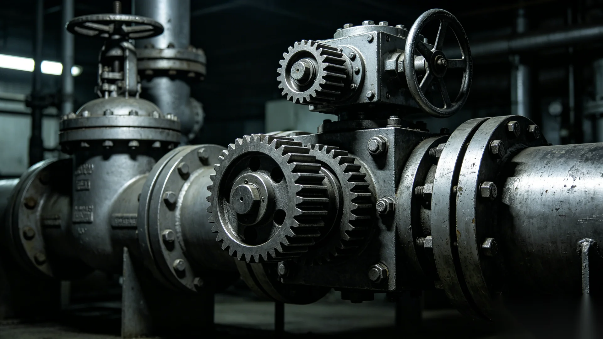
Quarter-turn worm gear operators convert handwheel effort into a controlled 90° rotation for butterfly, ball, and plug valves. The self-locking worm-and-wheel set multiplies input torque, holds the disc or ball at any position, and mounts to ISO 5211 top-flanges. Legacy reference entries cover catalog output torque from 200 N·m (M07) to 4,400 N·m (M16) on F05–F25 interfaces.
Before you specify
Start with the valve’s required angular travel and operating torque. Then confirm the flange, stem coupling, operating duty and available handwheel space.
| Selection check | Required input |
|---|---|
| Motion | Confirm the actual open-to-close angle and required stop positions. |
| Demand | Obtain breakaway, running and seating torque for the specified service. |
| Fit | Match the mounting drawing and coupling engagement before selecting the exact model. |
Download selection worksheet (PDF) Check the part-turn interface · Request a configuration review
References: Technical scope and product reference. Manufacturer documents describe their own products; confirm the exact offered configuration.
Application Foundation
A quarter-turn worm gear operator rotates a valve stem 90° between fully open and fully closed — the standard interface for butterfly, ball, and plug valves. The worm-and-wheel gearing multiplies handwheel torque so an operator can seat or unseat large discs by hand, with holding performance checked against the valve load and vibration conditions.
Size a quarter-turn operator from the valve break-to-open torque at design pressure, applying the documented project safety factor, then match the ISO 5211 flange and stem bore. The legacy reference M00 single-stage range below lists catalog output torque, ratio, input torque, maximum bore, ISO 5211 flange options, and weight for models M07 through M16.
Engineering Data
| Model | Output Torque (N·m) | Ratio | Input Torque (N·m) | Max Bore (mm) | ISO 5211 Flange | Weight (kg) |
|---|---|---|---|---|---|---|
| M07 | 200 | 40:1 | 19 | 25 | F05, F07 | 3.1 |
| M10 | 500 | 42:1 | 45 | 30 | F07, F10 | 6.2 |
| M12 | 1000 | 42:1 | 90 | 40 | F10, F12, F14 | 11 |
| M14 | 1800 | 60:1 | 110 | 60 | F12, F14, F16 | 14 |
| M14A | 2500 | 70:1 | 130 | 60 | F14, F16 | 21 |
| M15 | 3400 | 68:1 | 165 | 80 | F14, F16 | 32 |
| M16 | 4400 | 88:1 | 169 | 85 | F16, F25 | 44 |
Third-party benchmark source: legacy third-party reference catalog (M00 single-stage, manual quarter-turn). ValveWormGear does not claim these models as its own offering. Values are catalog nominal figures; final dimensions, ratings and drive details require confirmation from the named supplier — request a datasheet.
| ISO 5211 Flange | Typical Valve Size Band* | Common Valve Families | Reference Entries Offering This Flange |
|---|---|---|---|
| F05 | Small bore | Ball, plug, small butterfly | M07 |
| F07 | Small–medium bore | Butterfly (wafer), ball, plug | M07, M10 |
| F10 | Medium bore | Butterfly, ball, plug | M10, M12 |
| F12 | Medium bore | Butterfly (lug), ball, gate top-work | M12, M14 |
| F14 | Medium–large bore | Butterfly, trunnion ball, gate | M12, M14, M14A, M15 |
| F16 | Large bore | Butterfly (double flange / AWWA), ball, gate | M14, M14A, M15, M16 |
| F25 | Heavy / large bore | Large AWWA butterfly, high-pressure ball, large gate | M16 |
*Valve size band is indicative only — actual flange depends on the valve manufacturer's top-work, stem, and torque rating. Flange and legacy single-stage reference data are from the legacy reference catalog (M07–M16, 200–4,400 N·m). The reference catalog also contains separate higher-torque series; these are not IP67 or IP68 test declarations. Confirm the exact flange against your valve datasheet.
Operation
Quarter-turn worm gear operators use a worm on the input shaft driving a worm wheel keyed to the valve stem. For a single-start worm, one input revolution advances the wheel by one tooth, so ratios of roughly 40:1 to 88:1 (per the legacy reference catalog) reduce a small handwheel input to high stem torque. Self-locking depends on the selected geometry and friction conditions; confirm holding performance for the application.
Position indicators show open or closed travel, mechanical travel stops set the 90° end positions, and ISO 5211 drive bushings transmit torque to the stem. For actuated installations, the same quarter-turn footprint accepts a part-turn electric or pneumatic actuator in place of the handwheel.
Engineering
By Industry
Pipeline, refinery, and terminal isolation on butterfly, ball, and gate valves.
Intake, distribution, and process isolation valves in municipal and industrial plants.
Cooling-water, feedwater, and circulating-water valve actuation.
Slurry, tailings, and process water valves in abrasive duty.
Common Questions
A quarter-turn valve opens or closes with a 90° rotation of the stem. A butterfly disc, ball, or plug turns from full-open to full-closed in a single quarter revolution. A quarter-turn worm gear operator multiplies handwheel torque so an operator can move large discs by hand, and the self-locking worm holds the valve at any set position.
A quarter-turn operator rotates the stem 90° for butterfly, ball, and plug valves. A multi-turn operator needs many revolutions to drive a rising stem through its travel on gate and globe valves and is rated for axial thrust as well as torque. Selecting the wrong type causes insufficient travel or overload, so confirm valve type during sizing.
Self-locking depends on the worm geometry and friction conditions. Check the selected model's holding performance and required locking provisions; a quarter-turn designation alone does not prove self-locking.
Use a quarter-turn gear operator when a butterfly, ball, or plug valve requires more torque than a bare handwheel can supply, or when controlled, repeatable seating is needed. It also provides an ISO 5211 base for later actuation. Size it to the valve break-to-open torque with a documented project safety factor.
The legacy reference M00 single-stage quarter-turn range covers catalog output torque from 200 N·m (model M07) to 4,400 N·m (model M16), with ISO 5211 flanges from F05 to F25 and maximum bores up to 85 mm. Two-stage units extend higher torque for large-bore valves — request a datasheet for the full table.
Send your butterfly, ball, or plug valve torque, stem bore, and ISO 5211 flange. The cited third-party range may be used only as a preliminary comparison; final model selection and interface confirmation must come from the named supplier.
Specify the required torque, mounting drawing, operating environment and inspection documents together. A standard describes a classification or interface; the selected model needs its own confirmed specification.
For immersion duty, record the depth, duration, water conditions and seal arrangement. Specify cleaning jets separately. IP ratings do not establish corrosion resistance, and ISO flange compatibility does not establish gearbox output torque.
The single-stage comparison values were checked against the locally held seven-page valve gearbox catalog, page 2. They remain reference values; request the current model drawing and datasheet for your order.